INSTALLATION
Please click here for list of Installers by State.Procedures for GFT Hydrogen Generator®, also referred to as a "Hydrogen Cell."
IMPORTANT NOTES:
1. WINTER OPERATION - Hydrogen Generators®, like any other pieces of equipment exposed
to the elements, must be protected from freezing during cold weather. This can be accomplished by adding denatured alcohol in order to achieve a 20% alcohol solution. Initial cell fill-up would require the addition of no more than 1/2 liter of alcohol. Proper Generator working capacity is about 2 and 1/2 liters so, 2 liters of tap water added to 1/2 liter of alcohol equals an initial fill-up. When a Generator requires additional water for continued winter operation, be sure to include enough denatured alcohol to maintain the 20% alcohol solution. You can always keep a premixed jug in your vehicle.
2. This system should be installed by a person totally versed in automotive circuitry otherwise
damage to Hydrogen Generator® components and/or the vehicle can occur. The following instructions and procedures are for illustration ONLY and should not be used to actually install or operate a Hydrogen Generator®. Actual instructions and procedures are included with each Generator kit.
3. The Hydrogen Generator® circuit should be connected to a 12V circuit within the vehicle at
the Ignition switch or to a suitable source that is activated and deactivated when the engine is turned on and off. This is a safety feature that prevents the Hydrogen Generator® from operating while the engine is turned off.
UNIT PLACEMENT and MOUNTING
1. The most common place for mounting the H 2 Generator Canister Assembly is under the
hood, however, alternate locations are acceptable. Unit must be mounted in an upright position with the outlet slightly below the intake of the air filter connection source with appropriate bottom support or proper strapping.
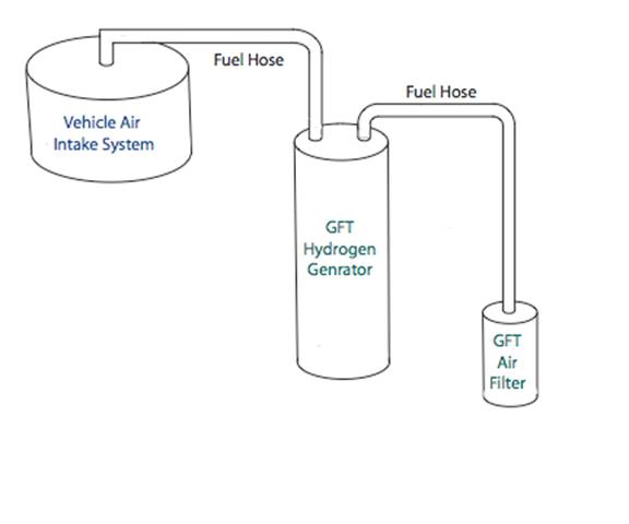
2. (See Figure 1) The supplied AIR FILTER is attached to one of the ½” barbed “L” fittings
on the top of the H 2 Generator unit. One end of the hydrogen supply hose is to be attached to the other ½” barbed “L” fitting on the top of the H 2 Generator unit and the other end of the hydrogen supply hose should be attached to the air intake system, after the MAF (Mass Air Flow) Sensor and before the Throttle Plate using supplied ½” barbed “L” fitting.
NOTE: IT IS RECOMMENDED THAT AUTOMOTIVE RATED FUEL LINE HOSE BE USED. IT CAN BE PURCHASED AT MOST AUTO PARTS DEALERS. ONE RECOMMENDED TYPE IS:
GOODYEAR EP SAE 30R9 CARB APPROVED (C-U-06-011)
(OTHER EQUIVALENTS ARE ACCEPTABLE)WARNING: DO NOT TAP HOSE FITTING HOLES IN AIR INTAKE PARTS WHILE STILL ATTACHED TO ENGINE. THE AIR INTAKE ENGINE AIR SUPPLY SYSTEM MUST BE REMOVED TO PREVENT SHAVINGS AND OTHER PARTICLES FROM ENTERING THE ENGINE -- POSSIBLE ENGINE DAMAGE COULD OCCUR
3. Place the California Air Resources Board E.O. Number or Exemption label (we will inform
you when we receive it) on or near the GFT Hydrogen Generator in the engine compartment; this is a smog check inspection requirement.
SYSTEM WIRING
(Refer to drawing 101035-System Wiring Diagram-with Relay)
1. For safety reasons, be sure ignition switch is “OFF” and battery is disconnected.
2. Wire the Ammeter Panel “HOT” wire (Inline 30 amp fuse) to supplied 30 amp relay, terminal #30.
3. The Ammeter Panel “GROUND” wire should be attached to a suitable ground source under the dashboard or other suitable location.
4. Connect the Ammeter Panel ( RED) “GENERATOR” wire to the ( RED) “GENERATOR” wire from the H 2 Generator canister.
5. Connect the Ammeter Panel “SENSOR” wire to the “SENSOR” on the H 2 Generator.
6. Wire 30 amp relay terminal #87 to Positive battery terminal.
7. Wire 30 amp relay terminal #86 to ground.
8. Wire 30 amp relay terminal #85 to “switched” 12 volt source (i.e., fuel pump). “Switched” 12 volt source refers to power that is “ON” when engine is running and “OFF” when engine is turned off.
INSTALLATION NOTES
1. There should be three wires leaving the vehicle cab from the Ammeter Panel through a 1/4” rubber grommeted hole at the bulkhead. (SENSOR, GENERATOR and HOT wires)
2. This hole must drilled away from any exhaust manifold location to prevent possibly overheating wires. If required, a variety of commercially available heat sink materials can be used.
SYSTEM CHARGING AND STARTUP
After installation of all wiring, supplied air filter, H 2 Generator canister and supply hoses, the system must be charged.
1. At the H 2 Generator unit, remove FILLER CAP on top of unit. Add to the canister approximately 4 oz. of SAN PELIGRINO mineral water.
2. Reconnect the vehicle battery and turn ignition “ON” and turn power switch at Ammeter Panel “ON”.
3. With someone to assist, slowly fill the canister with AQUAFINA drinking water until the “GREEN” LED on the Ammeter Panel starts to glow. “DO NOT OVER FILL THE CANISTER”
4. Turn the Ammeter Panel switch to “OFF” and start the engine. Turn the Ammeter Panel switch to “ON” and the ammeter should read between 3 – 7 amps.
5. As a safety measure, “Never Operate the H 2 Generator without the Engine Running”.
6. After the initial filling, the canister should be topped off whenever you fill up with fuel, with AQUAFINA water unless the amperage reading drops below 4 amps. At this point, the canister should be topped off with one or two ounces of SAN PELIGRINO MINERAL water again until the amperage settles into an average operating range of 4 to 10 amps.
7. Caution: if you add too much water, the system might need to be drained off (using drain cap at bottom-side of canister unit) until the level is just visible approximately ½ inch below the “Filler” fitting on top of unit.
8. BE SURE to tighten filler cap and drain cap securely. If the caps are not tightened securely, the intake vacuum system may be adversely effected possibly causing the engine to operate inefficiently.
9. After a few minutes of operation with the engine running, the amperage reading will settle to an ideal operating range of 4 – 10 amps.
10. The GREEN LED water level indicator on the Ammeter Panel will begin to dim and eventually go off when the system needs more water. This will generally occur once between or at fuel tank fill-ups, depending on gas tank size, engine displacement, ambient temperatures, etc…